4.14.2.11. FRPConfinedConcrete02
- uniaxialMaterial('FRPConfinedConcrete02', matTag, fc0, Ec, ec0, <'-JacketC', tfrp, Efrp, erup, R>, <'-Ultimate', fcu, ecu>, ft, Ets, Unit)
Figure 1 Hysteretic Stress-Strain Relation
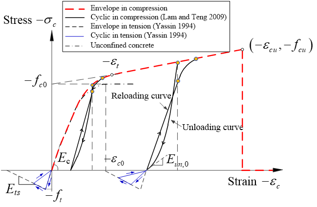
This command is used to construct a uniaxial hysteretic stress-strain model for fiber-reinforced polymer (FRP)-confined concrete. The envelope compressive stress-strain response is described by a parabolic first portion and a linear second portion with smooth connection between them (Figure 1). The hysteretic rules of compression are based on Lam and Teng’s (2009) model. The cyclic linear tension model of Yassin (1994) for unconfined concrete (as adopted in Concrete02) is used with slight modifications to describe the tensile behavior of FRP-confined concrete (Teng et al. 2015).
matTag(int)integer tag identifying material
fc0(float)compressive strength of unconfined concrete (compression is negative)
Ec(float)elastic modulus of unconfined concrete (=4730√(-$fc0(MPa)))
ec0(float)axial strain corresponding to unconfined concrete strength (≈ 0.002)
-JacketC(str)input parameters of the FRP jacket in a circular section
tfrp(float)thickness of an FRP jacket
Efrp(float)tensile elastic modulus of an FRP jacket
erup(float)hoop rupture strain of an FRP jacket
R(float)radius of circular column section
-Ultimate(str)input ultimate stress/strain directly
fcu(float)ultimate stress of FRP-confined concrete ($fcu ≥ $fc0)
ecu(float)ultimate strain of FRP-confined concrete
ft(float)tensile strength of unconfined concrete (=0.632√(-$fc0(MPa)))
Ets(float)stiffness of tensile softening (≈ 0.05 Ec)
Unit(float)unit indicator, Unit = 1 for SI Metric Units; Unit = 0 for US Customary Units
Note
Compressive concrete parameters should be input as negative values.
The users are required to input either the FRP jacket properties in an FRP-confined circular column (<-JacketC>) or directly input the ultimate point (εcu, fcu) (<-Ultimate>). If <-JacketC> is used, the ultimate stress and strain are automatically calculated based on Teng et al.’s (2009) model which is a refined version of Lam and Teng’s (2003) stress-strain model for FRP-confined concrete in circular columns. If <-Ultimate> is used, the ultimate stress and strain can be calculated by the users in advance based on other stress-strain models of FRP-confined concrete and thus can be used for other cross section shapes (e.g., square, rectangular, or elliptical). If none of them is specified, a stress-strain curve (parabola + horizontal linear curve) for unconfined concrete will be defined (Figure 1). Both <-JacketC> and <-Ultimate> adopt the envelope compressive stress-strain curve with a parabolic first portion and a linear second portion.
Unit indicator: $Unit = 1 for SI Metric Units (e.g., N, mm, MPa); $Unit = 0 for US Customary Units (e.g., kip, in, sec, ksi).
Calibration:
The implemented new material has been calibrated using a simple-supported Force-Based Beam-Column element subjected to axial load only (http://opensees.berkeley.edu/wiki/index.php/Calibration_of_Maxwell_Material). The output stress-strain responses were compared with the desired curves defined by the input parameters.
Examples:
Example 1: Pin-ended FRP-confined reinforced concrete (RC) columns
Figure 2 Simulation of pin-ended FRP-confined RC column
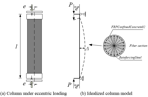
The first example is a pin-ended FRP-confined circular RC column subjected to eccentric compression (load eccentricity = 20 mm) at both ends tested by Bisby and Ranger (2010) (Figure 2). Due to the symmetry in geometry and loading, only half of the column needs to be modelled. In this case, three forceBeamColumn elements each with 5 integration points were used for the half column. The FRPConfinedConcrete02 model was used to describe the stress-strain behavior of FRP-confined concrete. Either <-JacketC> or <-Ultimate> can be used. If the former is used, the properties of the FRP jacket need to be input; if the latter is used, the ultimate stress and strain need to be calculated by the users and input directly. The eccentric loading is applied with a combined axial load and bending moment at each end node. An increasing vertical displacement is applied to the top node of the column model. The analysis terminated until the ultimate axial strain of FRP-confined concrete was reached by the extreme compression concrete fiber at the mid-height (equivalent to FRP rupture). SI Metric Unit (e.g., N, mm, MPa) is used in the script of this example ($Unit = 1).
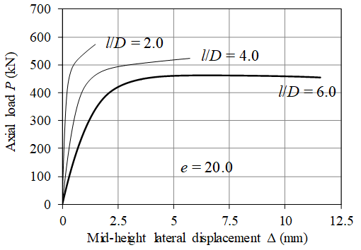
Figure 3 shows the comparison of axial load-lateral displacement curve between the test results and the theoretical results. Figure 4 shows the variation of column slenderness ratio (l/D) on the axial load-lateral displacement response of the column. Please refer to Lin (2016) for more details about the modeling.
Figure 3 Experimental results vs theoretical results
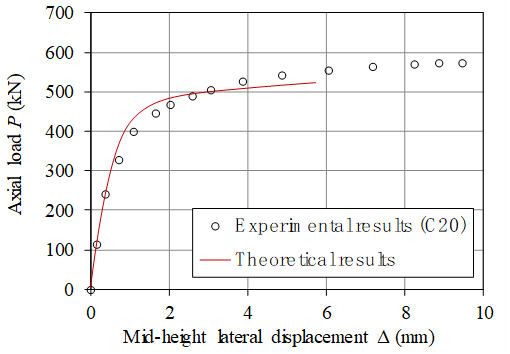
Figure 4 Parametric study (effect of column slenderness ratio)
Example 2: Cantilever column subjected to constant axial compression and cyclic lateral loading
Figure 5 Simulation of columns under cyclic latera loading

The second example is a cantilever FRP-confined circular RC column subjected to constant axial compression and cyclic lateral loading (Column C5 tested by Saadatmanesh et al. 1997). The US Customary Units (e.g., kip, in, sec, ksi) were used in this example. The twenty-five (25)-in.-height region (potential plastic hinge region) above the footing of the column was wrapped with an FRP jacket; the remaining portion of the column with a height of 71 in. was conventional RC section without FRP jacketing. The column was modelled using two forceBeamColumn elements to cater for the variation of section characteristic along the column height. A zero length section element at the column-footing interface was used to simulate fixed-end rotations due to the strain penetration of longitudinal steel bars (Figure 5) (Lin et al. 2012). The bond-slip model of Zhao and Sritharan (2007) (Bond_SP01) was used to depict the bar stress-slip response. In addition, another zero length section element was used at the column-footing interface to consider the possible rotations of the footing (Teng et al. 2015). The rotation stiffness of the zero length section element was adjusted to achieve close matching between the test response and the predicted response during the initial stage of loading. This zero length section element was found to have little effect on the ultimate displacement of the column (Teng et al. 2015). Moreover, the inclination of axial load in the column test needs to be accounted for when comparing predicted results with test results (Teng et al. 2015). Figure 6 shows the comparison of lateral load-lateral displacement curve between the test results and the theoretical results.
References:
Bisby, L. and Ranger, M. (2010). “Axial-flexural interaction in circular FRP-confined reinforced concrete columns”, Construction and Building Materials, Vol. 24, No. 9, pp. 1672-1681.
Lam, L. and Teng, J.G. (2003). “Design-oriented stress-strain model for FRP-confined concrete”, Construction and Building Materials, Vol. 17, No. 6, pp. 471-489.
Lam, L. and Teng, J.G. (2009). “Stress-strain model for FRP-confined concrete under cyclic axial compression”, Engineering Structures, Vol. 31, No. 2, pp. 308-321.
Lin, G. (2016). Seismic Performance of FRP-confined RC Columns: Stress-Strain Models and Numerical Simulation, Ph.D. thesis, Department of Civil and Environmental Engineering, The Hong Kong Polytechnic University, Hong Kong, China.
Lin, G. and Teng, J.G. (2015). “Numerical simulation of cyclic/seismic lateral response of square RC columns confined with fibre-reinforced polymer jackets”, Proceedings, Second International Conference on Performance-based and Life-cycle Structural Engineering (PLSE 2015), pp. 481-489 (http://plse2015.org/cms/USB/pdf/full-paper_7408.pdf).
Lin, G., Teng, J.G. and Lam, L. (2012). “Numerical simulation of FRP-jacketed RC columns under cyclic loading: modeling of the strain penetration effect”, First International Conference on Performance-based and Life-cycle Structural Engineering (PLSE2012), December 5-7, Hong Kong, China.
Saadatmanesh, H., Ehsani, M. and Jin, L. (1997). “Seismic retrofitting of rectangular bridge columns with composite straps”, Earthquake Spectra, Vol. 13, No. 2, pp. 281-304.
Teng, J.G., Lam, L., Lin, G., Lu, J.Y. and Xiao, Q.G. (2015). “Numerical Simulation of FRP-Jacketed RC Columns Subjected to Cyclic and Seismic Loading”, Journal of Composites for Construction, ASCE, Vol. 20, No. 1, pp. 04015021.
Yassin, M.H.M. (1994). Nonlinear Analysis of Prestressed Concrete Structures under Monotonic and Cyclic Loads, Ph.D. thesis, University of California at Berkeley, California, USA.
Zhao, J. and Sritharan, S. (2007). “Modeling of strain penetration effects in fiber-based analysis of reinforced concrete structuresconcrete structures”, ACI Structural Journal, Vol. 104, No. 2, pp. 133-141.